
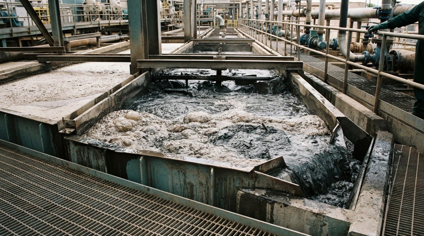
More air does not automatically improve flotation. Air creates bubbles that carry hydrophobic mineral particles into the froth, but excessive aeration and agitation can detach particles. These common flotation circuit problems often stem from the balance between airflow, pulp conditions and circuit configuration.
When recovery or concentrate grade drifts, it makes sense to check the cells and air supply first. But slime, pulp density, reagent delivery or changing feed may also be responsible, so adjusting airflow alone may not solve the problem.
This article explains how air affects bubbles and froth, how slime and pulp density influence separation and reagent use, and how circuit configuration shapes results. It also highlights practical symptoms to investigate, helping you connect performance changes with the process conditions behind them.
Key Takeaways
- Assess airflow alongside agitation and froth stability; increasing air alone may not improve particle recovery.
- Recognize how fine slime can contaminate froth and interfere with coarse-particle flotation, then consider feed preparation and reagent strategy.
- Match pulp density to ore characteristics and flotation stage rather than applying one setting across the circuit.
- Trace performance changes through feed conditions, reagent delivery and circuit configuration to identify where adjustments may help.
2. Slime effects on concentrate grade and reagent use
Very fine slime particles, usually smaller than 5 to 10 μm, can enter froth products and lower concentrate grade. They can also coat coarser mineral surfaces, making those particles harder to float. Desliming the feed with equipment such as hydrocyclones or spiral classifiers can reduce this interference before flotation. Water glass, soda ash and caustic soda are used to limit slime flocculation and surface covering, but their use depends on the ore and process chemistry.
Pulp mass fraction affects how much reagent reaches each unit of solids. When feed density changes, a fixed reagent addition may be too high or too low relative to the mineral mass. Track pulp density alongside reagent concentration and feed rate, then assess dosage against those changing conditions. Water quality matters too: raw-water characteristics can affect flotation, while dissolved substances may alter how reagents interact with mineral surfaces. Where possible, use plant-water samples in flotation tests and assess whether treatment or water reclaiming changes the response.
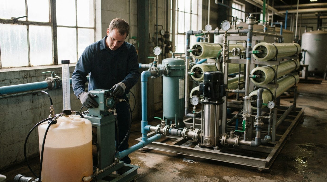
Consistent reagent preparation, preconditioning and dispersion are essential. Variable concentration, manual dosing, unstable ore feed and poor mixing can all lead to dosage fluctuations. Inject reagents where they can mix thoroughly with the pulp before the target flotation stage. Avoid stagnant zones and points close to pump suction, where dilution may fluctuate. Check that solutions are prepared consistently, dosing equipment delivers steadily, and conditioning allows time for reagents to contact mineral surfaces before the pulp enters the cells.
Air, reagent and pulp-level control issues can result from uneven airflow, blocked spargers, poor mixing, slurry surges, worn instruments or poorly tuned valves. Slow mechanical or float devices can also disrupt level control. Water quality and process chemistry affect bubble stability and reagent response, so changes in plant water may alter froth behaviour. Monitor airflow, pulp level, feed density, reagent concentration and froth condition together. In lead flotation, compare reagent addition at each stage with concentrate grade and recovery. Changing dosage without checking feed conditions can obscure the cause of a shift.
3. Pulp density by ore properties and flotation stage
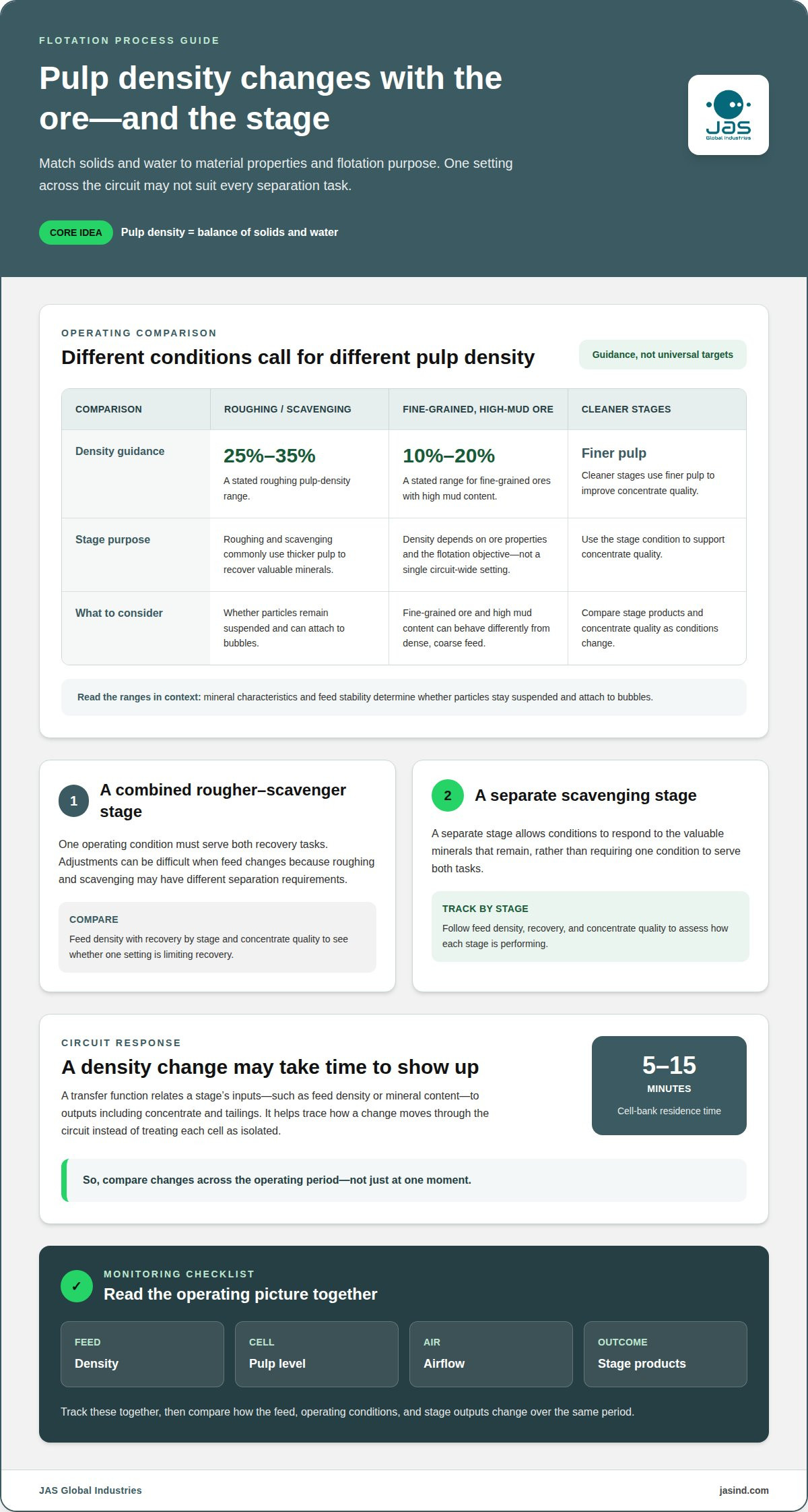
Pulp density is the balance of solids and water, and it influences particle suspension, bubble contact and mineral separation. More concentrated pulp may suit high-density minerals, while more dilute pulp may suit other conditions. Ore properties matter: dense, coarse feed behaves differently from fine-grained ore with high mud content. Match density to the material and flotation objective instead of carrying one setting through every stage.
Stage purpose also guides pulp concentration. Roughing and scavenging commonly use thicker pulp to recover valuable minerals, while cleaner stages use finer pulp to improve concentrate quality. A stated roughing range is 25%-35% pulp density; fine-grained ores with high mud content use 10%-20%. These are process conditions, not universal targets. Mineral characteristics and feed stability determine whether particles remain suspended and can attach to bubbles.
In a single-stage rougher-scavenger arrangement, one operating condition must serve both recovery tasks. This can make adjustments difficult when feed changes, because roughing and scavenging may have different separation requirements. A separate scavenging stage allows conditions to respond to the valuable minerals that remain. Compare feed density with recovery by stage and concentrate quality to see whether one setting is limiting recovery.
A transfer function describes how a stage’s input, such as feed density or mineral content, relates to its outputs, including concentrate and tailings. It helps show how a change moves through the circuit, rather than treating each cell as isolated. Cell-bank residence time ranges from 5 to 15 minutes, so stage responses may not appear immediately. Track feed density, pulp level, airflow and stage products together, then compare changes across the operating period.
When density shifts also alter collector demand, reviewing mining flotation collectors alongside stage conditions can help frame the process adjustment.
4. Flotation circuit configuration changes
Configuration determines where particles travel, which stages recover them, and where losses leave the flotation process. With six stages, more than 1,400 potential circuit configurations can be considered. Yet in studied cases, only three structures were optimal across a wide range of stage recoveries, out of 6,912 feasible structures. The practical lesson: compare routing options against actual feed and stage performance, not complexity alone.
Start by tracing each stream. If cleaner tailings contain material that has not been ground sufficiently, routing them to grinding classifiers allows further grinding before flotation. This can keep coarse material from passing through the rougher and disrupting pulp density. The route is most relevant when tailings analysis shows valuable particles remain locked or insufficiently liberated. Incoming ore characteristics help determine whether the change suits the operation.
Reagent placement may also change when stream routing changes. Staged addition along a flotation bank distributes reagent across successive cells and can improve recovery compared with adding it at a single point. The best arrangement depends on how mineral particles respond along the bank and where recovery declines. Review stage products before moving addition points, so changes address a specific loss rather than adding reagent without a process reason.
A lead flotation plant example shows why tailings destinations matter: after cleaner-scavenger tail was sent to final tail, final concentrate grade increased by 4% in that examined plant. This result illustrates a trade-off, not a universal prescription. Rejecting a stream can reduce circulating load and improve grade, but may also send recoverable mineral to final tail. Compare grade and recovery together before adopting the route.
In large-tonnage plants, parallel flotation units can divide production into lines, each with roughing, scavenging and suitable cleaning stages. A separate cleaning circuit is generally easier to regulate than a single-stage circuit and can limit the effect of feed variation on final grade. Configuration decisions should account for stream destinations, reagent addition and production goals. A targeted adjustment to one stage may be more useful than redesigning the entire bank.
4. What causes poor recovery and low concentrate grade in flotation?
Particle size is a direct recovery constraint. Ore particles larger than 0.1 mm and finer than 0.006 mm do not float well, so either fraction can carry valuable mineral into tailings. Review grinding performance and the size distribution when recovery falls. A suitable average can still conceal coarse or ultrafine fractions that reduce separation efficiency. These are common flotation circuit problems when feed characteristics shift.
Feed mineralogy can change as mining advances through an ore body. Differences in hardness, grindability, mineral content and floatability alter how particles respond to existing conditions. Compare feed characteristics with concentrate and tailings results as the feed changes. If recovery declines alongside a change in feed, flotation adjustments alone may not address the upstream cause.
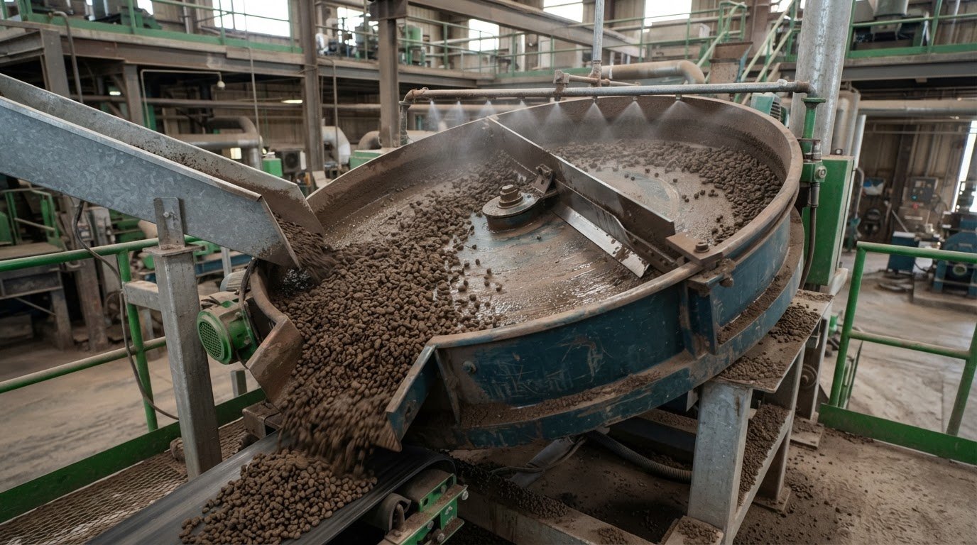
Cell conditions interact. Excessive aeration or agitation can detach mineral particles from bubbles, while uneven air delivery reduces the bubble surface available for collection. Fouled spargers, pressure drops, ageing valves and uncalibrated airflow meters can create differences between cells. Sanding, when coarse particles settle, reduces effective volume and weakens agitation. Inspect for deposits, uneven air distribution and worn launders, stators or rotors.
Preconditioning matters: if pulp is not conditioned sufficiently, early cells may effectively extend the conditioning step. Oxygen exposure can initially promote hydrophobicity in sulfide ore, but prolonged exposure can make mineral surfaces hydrophilic. Seasonal temperature shifts and reclaimed water can also change flotation response. The U.S. Bureau of Mines noted that minor mechanical difficulties and reagent experimentation caused day-to-day variation.
To diagnose common flotation circuit problems, compare particle size, feed mineralogy, density, airflow, pulp level and reagent concentrations against stage recovery and grade. Review level setpoints and instrument condition before changing several controls at once. This helps separate feed-driven losses from cell or control issues. Explore flotation performance options when process chemistry needs review alongside operating conditions.
JAS Global Industries: Mining Flotation Collectors
JAS Global Industries supplies Mining Flotation Collectors for operations reviewing reagent strategy alongside flotation performance. Collectors support mineral attachment to bubbles, making their selection and addition relevant when ore characteristics or recovery targets change. They are one part of a broader process: particle size, pulp conditions, water chemistry and circuit configuration also shape results.
Consider collector requirements when tests indicate that mineral response has shifted or current reagent practices are not supporting the intended separation. Reviewing feed characteristics and stage performance together helps define the operation’s chemical requirements. JAS Global Industries provides specialty chemical solutions for mining processes, aligning reagent choices with the demands of mineral processing.
Contact JAS Global Industries to discuss Mining Flotation Collectors for your operation.
Turn process observations into a focused next step
Use the next operating review to turn observations into a controlled decision. Record the production objective, proposed adjustment and expected response. Assign responsibility for reviewing the outcome so operational changes remain traceable across shifts and teams.
This approach helps distinguish a useful adjustment from a change that only adds complexity. If common flotation circuit problems persist, consider process and reagent factors together. A clear description of the operating challenge gives technical discussions a practical starting point and keeps attention on the plant’s needs.
For a discussion about flotation chemistry and your operation’s requirements, contact JAS Global Industries. A measured next step can help your team move forward with greater clarity.
Frequently Asked Questions
What is the main effect of air on flotation?
Air creates bubbles that carry attached hydrophobic mineral particles into the froth for separation. Its effectiveness depends on bubble formation and contact with particles, not simply on supplying more air. Excessive airflow can disrupt particle attachment through agitation; uneven air delivery between cells can lead to inconsistent recovery. Evaluate air alongside froth depth and mineral response at each stage.
How do you improve pulp level control in flotation cells?
Start by restoring reliable level measurements: clean and recalibrate the instruments, then review the controller response. If the level continues to swing, the cause may be slurry surges, a poorly tuned valve or a slow mechanical float device. Compare indicated levels with actual cell conditions during feed changes. This helps distinguish instrument drift from control-loop or process disturbances before operators adjust setpoints.
How do you float fine-grained materials?
Fine-grained material may be managed by reducing excess slime before flotation, then selecting conditions suited to the target mineral. Selective flocculation can separate target particles from gangue fines before flotation. Another approach attaches fine target-mineral particles to carrier particles; pyrite, for example, can carry fine-grained gold. The right route depends on mineral associations and whether fines are valuable or interfering with separation.
What causes sanding in flotation cells?
Sanding occurs when coarse particles settle instead of remaining suspended in a cell. Dense feed, weak agitation or an imbalanced grinding circuit can contribute. Look for deposits on the cell floor and compare their location with feed entry and mixing patterns. Settled solids reduce effective cell volume, which can weaken agitation and allow slurry to short-circuit.
What is flotation circuit management?
Flotation circuit management coordinates conditions across cells to maintain separation as feed and process conditions change. It considers airflow, pulp level, reagent dosing and feed density together. For example, interpret a change in feed density alongside reagent delivery and stage products rather than adjusting it in isolation. Process data is most useful when teams interpret it in context and act on related variables.
Why is my flotation froth unstable?
Froth stability can change when airflow, pulp level, reagent chemistry or slurry properties shift. Water chemistry also matters: according to the U.S. Environmental Protection Agency, agents in water modify surface tension to help form bubbles with suitable stability. Compare froth behaviour with recent changes in process water and operating conditions. This can help identify whether the disturbance is associated with air supply, chemistry or pulp.